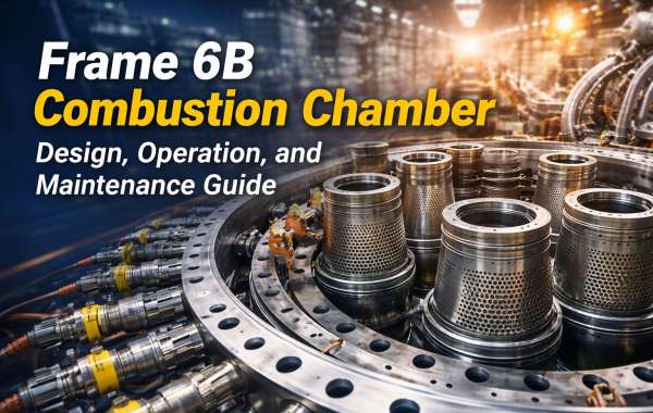
The Frame 6B combustion chamber is a critical component in heavy-duty gas turbines used for power generation and industrial applications. Widely recognized in the energy sector, the Frame 6B gas turbine is valued for its reliability, durability, and consistent performance. At the heart of this turbine lies the combustion chamber, where fuel and air mix and ignite to produce the high-energy gases that drive the turbine. Understanding its design, operation, and maintenance is essential for ensuring optimal efficiency and long service life.
Design of the Frame 6B Combustion Chamber
The Frame 6B combustion system typically features a multi-can (can-annular) design. This configuration consists of several individual combustion liners arranged around the turbine rotor. Each combustion chamber operates independently but contributes collectively to the turbine’s overall output.
Key design components include:
Combustion Liners: Cylindrical chambers where fuel combustion occurs.
Transition Pieces: Direct hot gases from the combustion liner to the turbine nozzle.
Fuel Nozzles: Precisely inject fuel into the combustion zone for efficient mixing.
Crossfire Tubes: Allow flame propagation between adjacent combustion cans during startup.
Flow Sleeves and Caps: Help manage airflow and cooling.
The materials used in the combustion chamber are typically high-temperature-resistant alloys designed to withstand extreme thermal stress, pressure, and vibration. Advanced cooling techniques, such as film cooling and thermal barrier coatings, help protect internal components from overheating.
Operation of the Frame 6B Combustion Chamber
The combustion process begins when compressed air from the turbine’s compressor section enters the combustion chamber. This high-pressure air mixes with fuel delivered through the fuel nozzles. The air-fuel mixture is ignited by spark plugs during startup, and once combustion is established, the flame is self-sustaining.
The combustion process generates high-temperature, high-velocity gases that expand through the transition pieces and into the turbine section. These gases spin the turbine blades, converting thermal energy into mechanical energy, which is then used to generate electricity.
Proper airflow distribution is crucial during operation. The system must maintain a balanced air-to-fuel ratio to ensure complete combustion, minimize emissions, and prevent issues such as flame instability or hot spots. Monitoring systems continuously track temperature, pressure, and vibration to maintain safe and efficient operation.
Maintenance of the Frame 6B Combustion Chamber
Routine maintenance is essential to extend the life of the Frame 6B combustion system and prevent costly downtime. Combustion components are exposed to extreme temperatures and mechanical stress, which can lead to wear over time.
Common maintenance activities include:
Visual Inspections: Checking liners, transition pieces, and fuel nozzles for cracks, distortion, or corrosion.
Non-Destructive Testing (NDT): Detecting hidden flaws using methods like dye penetrant or ultrasonic testing.
Fuel Nozzle Cleaning and Calibration: Ensuring proper spray patterns and combustion efficiency.
Replacement of Worn Parts: Swapping out damaged liners or transition pieces during scheduled outages.
Maintenance intervals are typically based on operating hours and manufacturer recommendations. Implementing predictive maintenance strategies—such as performance trending and combustion dynamics monitoring—can help detect early signs of failure and improve reliability.
Conclusion
The Frame 6B combustion chamber plays a vital role in gas turbine performance. Its robust can-annular design, precise fuel-air mixing process, and advanced cooling systems enable efficient and reliable power generation. By understanding its design, ensuring proper operation, and following disciplined maintenance practices, operators can maximize efficiency, reduce emissions, and extend the turbine’s operational lifespan.